
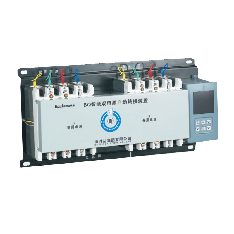
General
BQ series dual power automatic transfer switch is suitable for power supply system with AC 50/60Hz, rated working voltage AC400V, rated working current 800A and below.
It is possible to select and switch between two power sources according to requirements, ensuring uninterrupted operation of key power sources. When one power supply has overvoltage, undervoltage or phase loss, it will automatically switch to another power supply or start the generator.
Built-in RS485 communication interface, communication protocol MODBUS-RTU, realize real-time data upload, remote data configuration and status monitoring, as well as remote control, telemetry, remote control and remote adjustment functions.
Mainly used in hospitals, shopping malls, banks, hotels, high-rise buildings, fire protection and other places that do not allow long-term power outages with uninterrupted power supply required.
1.Can work in the environment of -5°C~40°C
2.The altitude of the installation site does not exceed 2000m
3.When the highest temperature is +40°C, the relative humidity of the air should not exceed 50%
4.Higher humidity is allowed at lower temperature, 20°C-90%
5.Standard: IEC 60947-6-1
Selection
BQ | 125 | M | 3 | 100A | W2 |
Product name | hell frame grade | Breaking capacity | Number of poles | Rated current | Controller code |
BQ:Dual power automatic transfer switch | 63: (10-63A) | M: Standard type | 3:3P 4:4P | 10、16、25、 32、40、 50、63、 80、100、 125、140、 160、180、 200、225、 250、315、 400、500、 630、800、 | Default:LED Y: LCD W2: Split LED display W3: Split LED display |
Working conditions
1.Can work in the environment of -5°C-40°C
2.The altitude of the installation site does not exceed 2000m
3.When the highest temperature is +40°C, the relative humidity of the air should not exceed 50%
4.Higher humidity is allowed at lower temperature, 20°C~90%
Function Introduction
Function | Full-function type |
Manual mode | ■ |
Automatic mode | ■ |
Motor protection function | ■ |
Main contact working position ( performing circuit breaker) | |
Normal power supply closed | ■ |
Reserve power supply closed | ■ |
Double break | ■ |
Automatic control | |
Monitoring normal power supply | ■ |
Monitoring reserve power supply | ■ |
Self-throwing and self-reset | ■ |
Self-throwing and non self-reset | ■ |
Reserve for each other | ■ |
Power grid-power grid | ■ |
Power grid-power generation | ■ |
Phase failure instantaneous protection | ■ |
Under-voltage protection 150-210V | adjustable |
Over-voltage protection 230-300V | adjustable |
Fire control function | ■ |
Changeover time delay0-240s continuously adjustable | ■ |
Returning time delay0-240s continuously adjustable | ■ |
Frequency display | ■ |
Communication function | optional |
Indication | |
N on/R on/double break indication | ■ |
Normal power supply indication | ■ |
Reserve power supply indication | ■ |
Fault tripping indication | ■ |
Parameter setting indication | ■ |
Voltage realtime indication | ■ |
Normal three phase voltage protection | three phase |
Reserve three phase voltage protection | three phase |
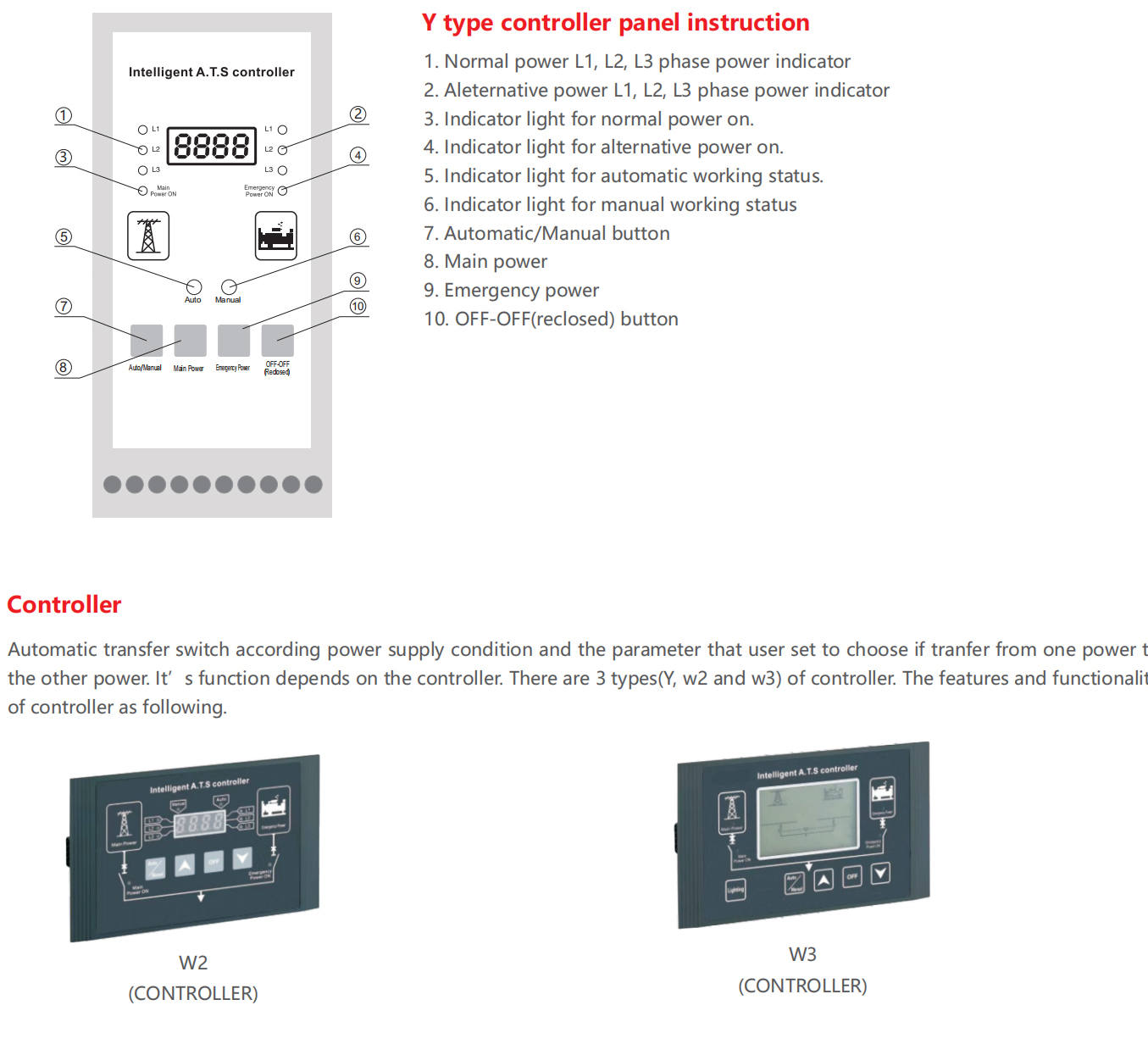
Controller | Y type Controller | W2 type Controller | W3 type Controller | |
Working power supply | AC160-250V 50/60Hz | DC12V (Provided by the inside OF y TYPE CONTROLLER) | ||
Installation | Integral type | Split type | ||
Position | 3 Positions | |||
Mode of operation | Auto, manual and electro-manual operation | |||
Voltage monitoring function | 3 phase over-voltage, under-voltage and phase loss monitoring | |||
Frequency monitoring function | Frequency monitoring | |||
Generator control | A set of 3A relay dry contact | |||
Fire linkage control | Passive contact input, with a set of normally open passive signal feedback contact | |||
Mode of conversion | According to users requirement could set at A uto Can set at Auto transfer and auto recover,Auto transfer and non-auto recovery or utility generator type mode according to user's requirement. | |||
Display | LED display | LED display | ||
Conversion time delay | 0.5s-60s continuously adjustable | |||
Return time delay | 0.5s-60s continuously adjustable | |||
Model | Match circuit breaker | Pole | Rated short circuitmaking capacity(Icm) | Rated short circuitbreaking capacity(Icn) | Rated currentof circuit breaker(A)10 , 16, 20, 3240 , 50, 63 | Rated insulationvoltage(V) 690 |
BQ-63 | BM1-63 | 3 | 31.5 | 15 | ||
4 | 31.5 | 15 | ||||
BQ-125 | BM1-125 | 3 | 52.5 | 25 | 16, 20, 32 , 40 ,50, 63 , 80 , 100, 125 | 690 |
4 | 52.5 | 25 | ||||
BQ-250 | BM1-250 | 3 | 52.5 | 25 | 125, 160, 180,200, 225, 250 | 690 |
4 | 52.5 | 25 | ||||
BQ-400 | BM1-400 | 3 | 73.5 | 35 | 250, 315, 350, 400 | 690 |
4 | 73.5 | 35 | ||||
BQ-630 | BM1-630 | 3 | 73.5 | 35 | 500, 630 | 690 |
4 | 73.5 | 35 | ||||
BQ-800 | BM1-800 | 3 | 73.5 | 35 | 700, 800 | 800 |
4 | 73.5 | 35 |
Switching device installation: After fixing the switching device, according to the rated current to choose the appropriate wires to wire.
Note: The phase sequence of main power and emergency power must be consistent.
Split type controller installation:
Use 2 strutting pieces to fix the split type controller on the panel.
Please check if the controller has been plugged into switching device and fastening screw. Please check whether each electric contact part is reliable and the fuse if good.
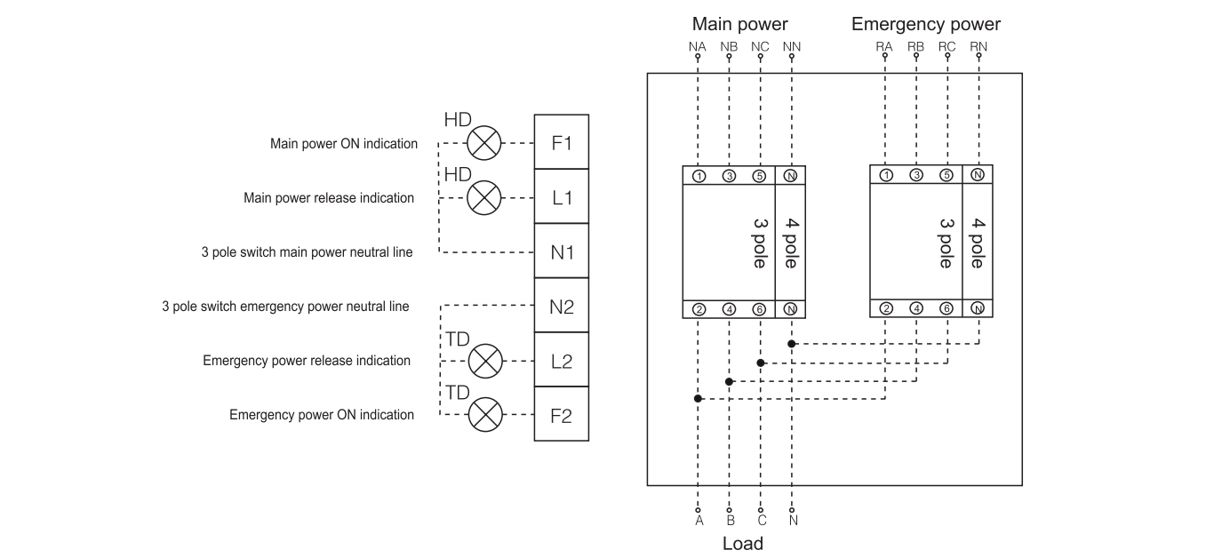
If user wants to withstand voltage test, please remove the controller first. Otherwise the controller will be broken down. For the 3 pole switch, user needs to connect main power neutral line to terminal N1 port.
Connect emergency power neutral line to terminal N2 port. Neutral line must be reliable and don't connect wrong so that ATS could proper work.
For the 4 pole switch, main and emergency power neutral line must be connected to the corresponding circuit breaker N pole. In addition,switching device should ground connection at the grounding mark.
User could connect indicator light to the terminal for observation. Refer to the wiring diagram below.
Note:
This diagram applies to three-phase four-wire. When using three-phase three-wire system, the neutral line of main power connects to terminal N1 port,neutral line of emergency power connects to terminal N2 port.
HD main power indication AC220V(User-provided).
TD main power indication AC220V(User-provided).
Overall and mounting dimensions(mm)
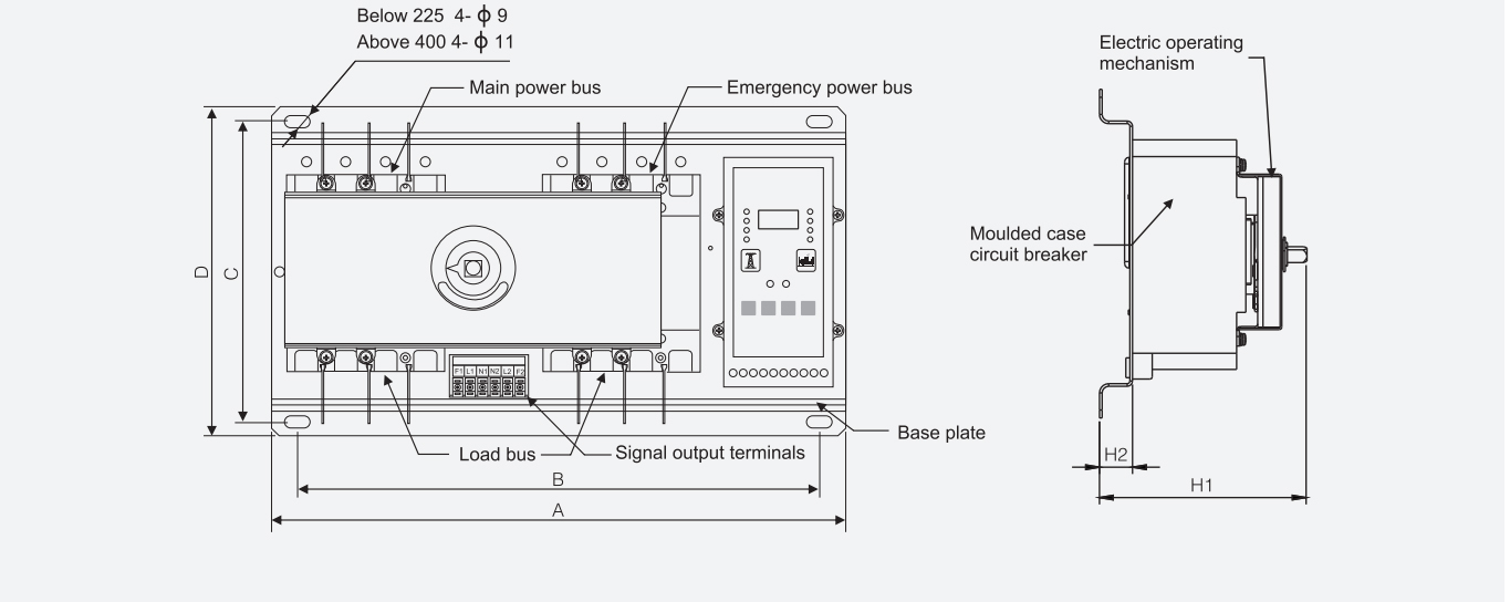
Dimensions Specification | A | D | B | C | H1 | H2 | ||
3P | 4P | 3P | 4P | |||||
BQ-63 | 380 | 405 | 250 | 340 | 365 | 230 | <160 | 25 |
BQ-125 | 405 | 435 | 250 | 365 | 395 | 230 | <170 | 25 |
BQ-250 | 450 | 480 | 250 | 410 | 440 | 230 | <190 | 25 |
BQ-400 | 570 | 620 | 330 | 510 | 560 | 300 | <200 | 25 |
BQ-630 | 680 | 740 | 330 | 620 | 680 | 300 | <250 | 25 |
BQ-800 | 750 | 820 | 330 | 690 | 760 | 300 | <250 | 25 |


