
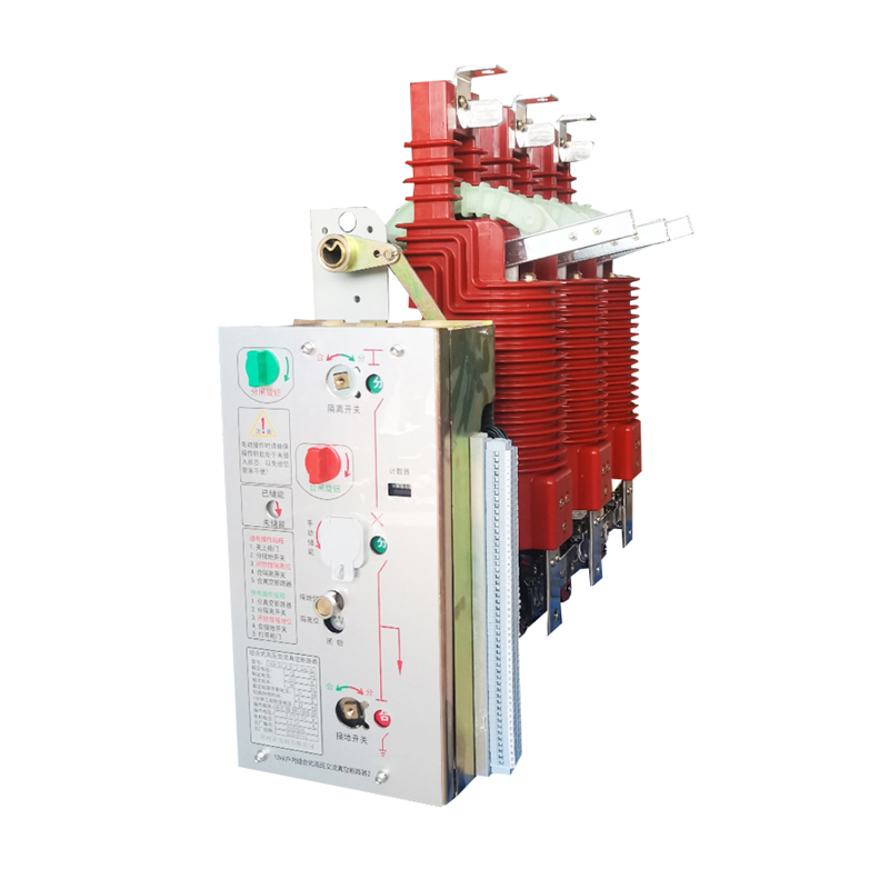
Product overview
Three-station indoor vacuum circuit breaker is a kind of high-voltage switchgear which integrates the functions of circuit breaker and disconnector, and is specially designed for indoor installation (usually used for medium-voltage switchgear, such as KYN28 and KYN61). Its core feature is that it has three clear and interlocking stations (positions):
Closing position: the main circuit is on, and the circuit breaker is closed, which can carry rated current and break fault current.
Switch-off position: the main circuit is disconnected and the circuit breaker is in the open state. At this time, there is a prescribed insulation distance and reliable fracture between the moving and static contacts.
Grounding position: the main circuit is disconnected, and the incoming side or outgoing side (usually load side or cable side according to the design) of the main circuit is reliably grounded through the grounding switch inside the circuit breaker body, providing safety protection for maintenance.
Core structure and working principle
Vacuum interrupter: the core component, which uses high vacuum environment as insulation and arc extinguishing medium. When the current is interrupted, the metal vapor arc generated between the contacts can quickly spread and extinguish in a vacuum environment.
Three-station mechanism: unique mechanical transmission and operation mechanism. Through a set of operating mechanism (usually spring energy storage operating mechanism) and a rotating shaft, the moving contact of vacuum interrupter and the moving contact of grounding switch are driven.
When the mechanism drives the moving contact to rotate to contact with the static contact of the main circuit, it is the closing position.
When the mechanism drives the moving contact to rotate away from the static contact of the main circuit and does not touch the grounding contact, it is the opening position (isolation fracture is established).
When the mechanism continues to drive the moving contact to rotate and make it reliably contact with the static contact of the grounding circuit, it is the grounding position (the load side of the main circuit is grounded).
Insulation structure: Insulating parts (such as insulating tie rods and insulators) usually cast or pressed with high-quality insulating materials such as epoxy resin or SMC (sheet molding compound) to ensure the insulation strength between phases, phases and fractures.
Operating mechanism: spring energy storage operating mechanism is widely used. Energy can be stored electrically (by motor) or manually. Opening and closing operations can be either electric (electromagnet or permanent magnet mechanism) or manual. The mechanism is internally designed with strict mechanical interlocking to ensure that:
Only when the circuit breaker is in the "opening position" can it be operated to the "grounding position".
Only when the circuit breaker is in the "opening position" can it be operated to the "closing position".
When in the "closing position" or "grounding position", mutual conversion operation cannot be performed.
Prevent the disconnector from opening/closing under load (i.e. operating from the opening position to the grounding position or vice versa, it must be carried out under no load).
In addition to the internal interlocking of the mechanism, the interlocking device usually cooperates with the "five-prevention" interlocking system of the switch cabinet (for example, through the position of the chassis and the locking of the cabinet door, etc.) to achieve comprehensive safety protection and prevent misoperation.
Technical parameter
Parameter category | Parameter name | Unit | Typical value range | Explain |
Rated parameter | ||||
rated voltage | kV | 12, 24, 40.5 | MaximUm system voltage (um) | |
rated frequency | Hz | 50 / 60 | ||
rated current | A | 630, 1250, 1600, 2000, 2500, 3150, 4000 | The working current that the circuit breaker can bear for a long time | |
Rated short-circuit breaking current | kA | 20, 25, 31.5, 40, 50 | The effective value of the maximum short-circuit current that the circuit breaker can break. | |
Rated short-term withstand current | kA | 20, 25, 31.5, 40, 50 | Effective value and duration of short-circuit current that circuit breaker can bear in closing position. | |
Rated short circuit duration | s | 3, 4 | Usually 3 or 4 seconds. | |
Rated peak withstand current | kA | 50, 63, 80, 100, 125 | Peak short-circuit current that the circuit breaker can withstand in the closing position (usually =2.5 x Isc) | |
Rated short-circuit closing current | kA | 50, 63, 80, 100, 125 | The maximum expected short-circuit current peak that the circuit breaker can close. | |
Rated operating sequence | - | O-0.3s-CO-180s-CO | Automatic reclosing operation sequence (minute -0.3 seconds-closing -180 seconds-closing) | |
Dielectric level | ||||
Rated lightning impulse withstand voltage (peak value) | kV | 75 (12kV), 125 (24kV), 185 (40.5kV) | Alternately and oppositely | |
kV | 85 (12kV), 145 (24kV), 215 (40.5kV) | Between fractures (isolated fractures) | ||
Rated power frequency withstand voltage (1min) | kV | 42 (12kV), 65 (24kV), 95 (40.5kV) | Alternately and oppositely | |
kV | 48 (12kV), 79 (24kV), 118 (40.5kV) | Between fractures (isolated fractures) | ||
Time parameter | ||||
Opening time | ms | ≤ 50 - 65 | Time from the opening command to the separation of all polar arc contacts. | |
Closing time | ms | ≤ 75 - 120 | Time from closing command to contact of all pole contacts. | |
Interruption time | ms | Opening time+arcing time | ||
Arc time | ms | ≤ 10 - 20(usually) | Time from contact separation to arc extinction. | |
On-off time (metal short circuit time) | ms | ≤ 50 - 70 | Time from the moment of contact in closing operation to the moment of contact separation in the next opening operation. | |
Mechanical properties | ||||
Mechanical life | 次 | 10,000 - 30,000 | The number of operation cycles when the main circuit is not charged (usually, it is divided into one). | |
Rated current breaking times | 次 | 10,000 - 20,000 | Number of times of interrupting rated current | |
Rated short circuit breaking times | 次 | 20 - 100 | Number of times of interrupting rated short-circuit current | |
Energy storage time | s | ≤ 15 (electric) | Time required for motor energy storage | |
Grounding switch parameters | ||||
Rated short-term withstand current | kA | Same as the main circuit or slightly lower | Short-circuit current that grounding switch can bear and its duration | |
Rated short circuit duration | s | 3, 4 | Usually the same as the main circuit | |
Rated peak withstand current | kA | Same as the main circuit or slightly lower | ||
Rated short-circuit closing current | kA | Same as the main circuit or slightly lower | The maximum expected short-circuit current peak that the grounding switch can close (usually used for troubleshooting grounding). | |
Mechanical life | 次 | 1,000 - 5,000 | Grounding switch operation times | |
Other parameters | ||||
Allowable wear thickness of dynamic and static contacts | mm | 2 - 4 | ||
Main circuit resistance | μΩ | Refer to the manufacturer's specific model sample. | Measured at rated current, the smaller the value, the better. | |
Operating voltage (auxiliary circuit) | V DC | 24, 48, 110, 220 | Energy storage motor, switching coil and control loop voltage | |
V AC | 110, 220 | |||
The protection grades | IP | IP4X (shell), IP2X (cabinet) | Solid foreign body prevention and waterproof grade | |
Weight | kg | 60 - 200+ | Increase with the increase of rated parameters | |
Installation mode | - | Fixed/handcart type (drawout type) | ||
Summary
Three-station indoor vacuum circuit breaker is the core equipment in modern medium voltage distribution system, which is widely used for its advantages of integrated function, safety, reliability, convenient operation, less maintenance and environmental protection. Understanding its "three-station" design concept, core structure, working principle and key technical parameters is very important for the correct selection, installation, operation and maintenance of equipment and the safe and stable operation of power system. Be sure to use the official technical data provided by the equipment manufacturer as the basis.


