
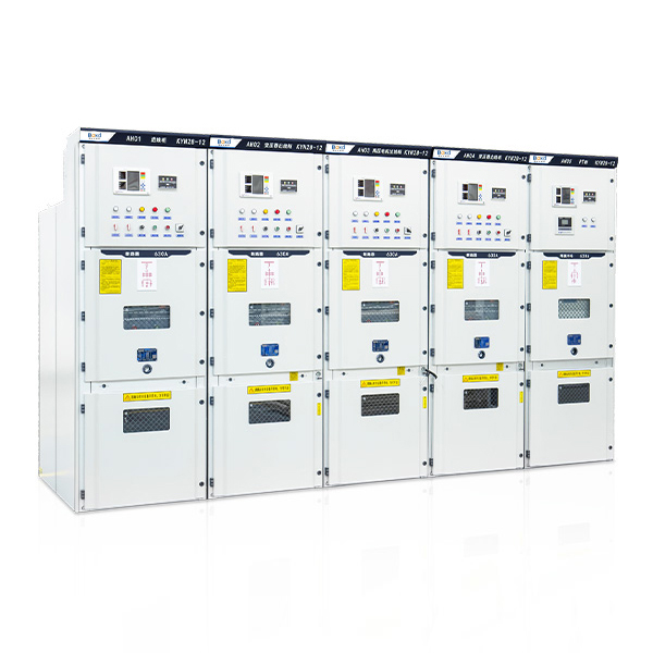
This equipment is indoor metal armoring with drawable switchgear (hereafter refer to as switchgear. 3.6-12kilovolt three phase AC 50Hz single bus bar and the single bus bar subsection system's omplete electricity distribution equipment is used in the power plant, small and medium-sized generator power transmission, industry and mining business power distribution as well as electrical industry system's second transformer substation's electric take-over , power transmission and large-scale high pressure motor starting and so on. The purpose is to control, protect and monitor. This switch equipment is up to the standard of IEC298、GB3906 and can prevent the charge from pushing and pulling the breaker, from opening and closing the breaker, from insulation with electricity by mistaken, from earthed switch closing the breaker ,from opening the switch's interlock when it with electricity mistakenly. It can not only use with VS1 vacuum circuit-breaker, but with Corporation's VD4 vacuum circuit-breaker. It is indeed a kind of power distribution equipment with superior performance.
Use environmental conditions
1.Normal condition
a.Surrounding air temperature:-10℃~ +40℃
b.Altitude : 1000M
c.Relative environment humidity: The daily relative humidity average is not higher than 95%, the monthly relative humidity average is not than higher 90%
d.Earthquake : The intensity does not exceed 8 degree.
e.The surrounding air without corrosive or flammable gas or water vapour.
f.Without a lot of dirtiness and regular fierce vibration, under the severe condition, the intensity meets the first kind requirement.
2.special working conditions
When it is used beyond the normal environmental condition stipulated in the GB3906, the user should consult with the manufacture.
Structure Introduction
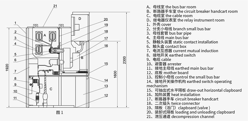
The switch equipment is designed according to GB3906-91 metal armoring seal switch equipment. The rectifier body is made up of the cabinet body and draw-out parts (namely handcart) placed in the middle. See charter 1. The cabinet divides into four separate rooms, the outer covering protection grade is IP4X,when each small room and the circuit breaker is opened, the protection grade is IP2X.It can suspend the inlet, outlet line, cable's inlet, outlet line and other function plan. After arranged and combined, it can become each kind of plan form of the power distribution equipment. This switch equipment may be installed and maintained from the frontage, therefore it may compose the dual arrangement back to back and be installed against the wall, improving the switch equipment's security and flexibility and making full use of the occupying area.
The main technical parameters
Sr. | Content | Unit | Value | |
1 | Bated Voltage | kV | 12 | |
2 | Rated Current | A | 630~4000 | |
3 | Bated Frequency | Hz | 50/60 | |
4 | Power Frequency Withstand Voltage in 1 min | Phase,Earthed | kV | 42 |
solating Fracture | kV | 48 | ||
5 | Lightning Impulse Withstand Voltage(Peak) | Phase,Earthed | kV | 75 |
Isolating Fracture | kV | 85 | ||
6 | Rated Current of the Main Busbar | A | 630~4000 | |
7 | Rated Current of the Branch Busbar | A | 630~4000 | |
8 | Rated Short-circuit Breaking Current | kA | 20/25/31.5/40/50 | |
9 | Rated Short Circuit Making Current | kA | 50/63/80/100/125 | |
10 | Rated Short-time Withstand Current(4s) | kA | 20/25/31.5/40/50 | |
11 | Rated Peak Withstand Current | kA | 50/63/80/100/125 | |
12 | Frequency Withstand Voltage in 1 min of Aux Control Loop | V | 2000 | |
13 | Internal Arc Duration Test(0.5s) | kA | 31.5~40 | |
14 | Rated Voltage of Aux Control Loop | V | AC or DC 110/220 | |
15 | Degrees of Protection | IP | P4X(IP2X when the front door is opened) | |
Switchgear structure diagram
Switchgear Dimensions
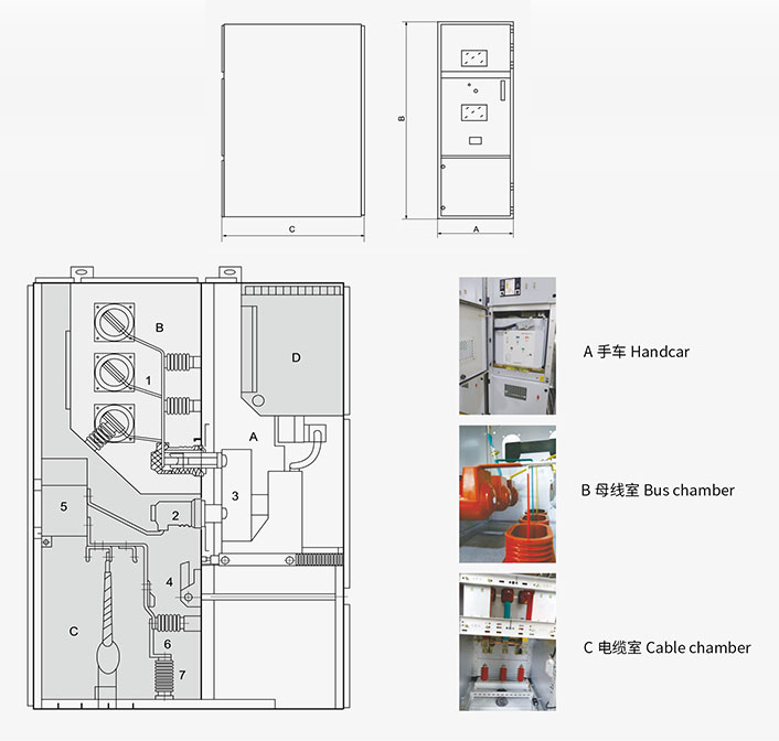
Handcar
The framework of handcart is made of steel sheet through the procession of CNC machine tool and rivet welding. According to the application, the handcarts can be divided into circuit breaker hand-cart, voltage transformer handcart, isolating handcart and metering handcart, etc. The handcarts of the same specification can be exchanged conveniently. In the cabinet, the handcart has isolating position, testing position and operating position, each of which is designed with a location device to assure that the handcart can't move easily at the above-mentioned positions, while the interlock must be unlocked to move the handcart.
Bus chamber
The bus is led from one switch cabinet to another one and fixed with static contact box through branch bus. The flat branch bus is connected through the bolt to the static contact box and main bus, not needing any other line clamps or insulators. When there is special demand of the clients or the project, the connecting bolt on the bus bar can be encapsulated with insulation and end cap. When the bus crosses the baffle of the switch cabinet, fix it with bus bushing, so that, if there is any internal fault arc, it can prevent the fault spreading to another cabinet and can guarantee the me-chanical strength of the bus.
Cable chamber
Inside the cable chamber, the current transformer, grounding switch, arrester and cable can be installed, and on the bottom is designed slotted removable aluminum sheet to assure the convenient siteconstruction.
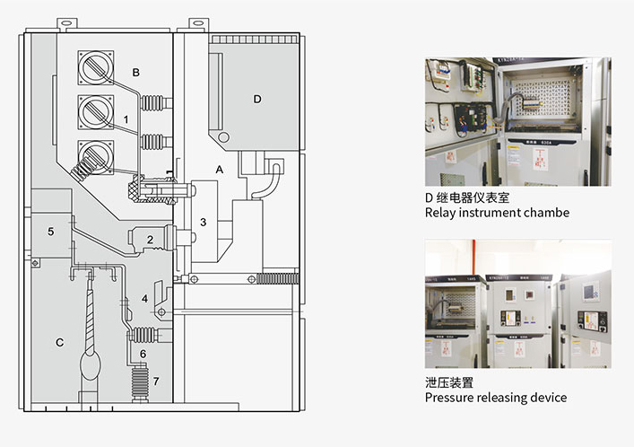
Relay instrument chamber
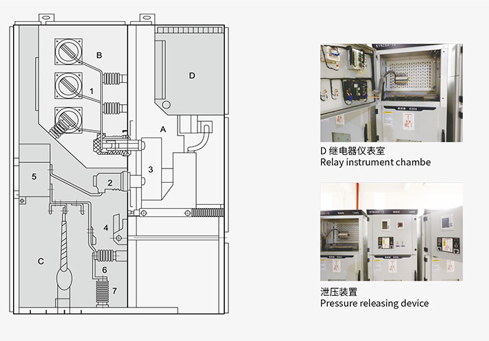
Relay instrument chamber is used to install all kinds of components, such as relays, instruments, signal indicator and operating switch, etc. In addition, it's available to add a small bus chamber on the top of the instrument chamber according to the demand of the clients, and set 16 lines to control the small bus.
Pressure releasing device
On the handcart chamber, bus chamber and cable chamber is installed pressure releasing device. When there is internal fault arc in the breaker, main bus or inside the cable chamber, and with the appearance of electric arc, the internal pressure in the switch cabinet rises. After it rises to a certain pressure, the pressure releasing metal sheet of the top device will be opened automatically, and the pressure and the gas are released to guarantee the safety of the operator and the switch cabinet.
Latching device
Latching device is used to connect the central exit and cabinet body, and the lifting device is also designed to make it more convenient to open the central exit. When the central exit stays closed, the connecting strength with the cabinet body is the best and the capability against the internal arcing fault effectively is strengthened.


